![]()
Join 20 other subscribers
An updated version of this post is available here.
Image Inpainting is the art of filling in lost portions of an image using background details in a visually plausible way. I came across this topic while searching for projects in the field of image processing for sixth semester. The moment I saw a few sample pictures, I decided that I was gonna work on it.
Here are a few pics of what we achieved in the end using our software:
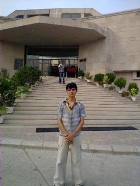
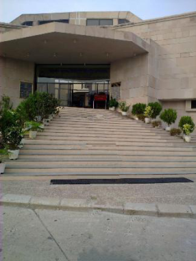
As is quite clear from these images, a good and fast algorithm for Image Inpainting can be really useful. I worked with Sapan to develop the software. We started with a traditional algorithm but finally ended up making several changes to it in order to improve the results.
Here’s a brief decription of the inpainting algorithm.
This is a very brief overview of the inpainting algorithm. For more details, you may feel free to contact me or go through the research paper that we authored.
For more information about the implementation, visit our project page on Sourceforge. I hope that you would enjoy using it. It is still a very early release and we hope to improve on it soon. Looking forward to your participation on the project as well.
See the software in action in this video.
Stay tuned for my next post. Meanwhile, tell me your suggestions/comments about my work.

Dear sir,
I also want to do my study in the field of image inpainting, so i need your help how i go through it. please guide me
Sure.
I think you should start reading some research papers on this. If you encounter any problem, feel free to ask here.
Hi Pulkit,
Did you try this algorithm with small region like 10×10 pixels?
I got problem with my code in small with high contrast
Hi,
By region of 10×10 pixels, do you mean the patch size? I have tested the algorithm with a patch size of 9×9 pixels as well as 3×3 pixels.
Can you mail me the image that you are working with?
hi sir
i am in final year
i am doing project on image inpainting
we do our project in java
i hav some doubt
we hav take ieee papers for references
in this there is some many equations
i cant understand it carefully plz give some idea to understand it
plz give some idea to find the pixels in the image except in the masked region
Hello,
For this you need to iterate through your image looking for patches that best correspond to the patch in question. This can be done by using some error measure. We use Mean Squared Error to calculate patch similarity. I hope this answers your question.
hi
thank you for your reply
we studied mean squared error algorithm but we cant understand clearly
plz explain for me clearly
hi
how r u
we hav just identified the masked region
we hav no idea to proceed further so plz guide me
but we hav no idea of how to map the pixels in that area
we hav some doubt on corespondence map
After defining the mask region, you need to find the boundary of the mask. This can be done by using any traditional gradient method like the forward difference method. Once you have the boundary of the masked region, you can then calculate the priorities of all the patches on the boundary of the unknown region and then try to fill the highest priority patch. This can be done by finding the patch from the background that has the lowest mean squared error as compared to the known pixels of current patch. The mean squared error is just the sum of squares of differences between corresponding pixel values between the source patch and the target patch. I hope its clear to you now.
hi
thank u for your guidance
we understand it and we are now going implement it
plzz
send the code in java
You can gt the code here.
pls send the code in java!!!!!!!!!!!sir
thank u sir
but we cant download the source code from the link
Go to the downloads tab. Here.
thank u so much!!!!!
sir!!!!!!!!!!!!!!!!!!!!!1
thank you so much brother!!!!!!!!!!!!!!!!!!
we hav execute the code and get the answers
thank you
we are very happy now
thank qqqqqqqqqqqqqqqqqqqq!!!!!!!!!!!!!!!!!!!!!!!!!!!!!!!!1
Message Deleted!
Gradient is used in data term to give importance to the structural features in the image. The exemplar technique is looking at the image in patches and then filling the patch with the maximum priority. This refers to the patch that we have a high confidence in filling (because we know many of its pixels already). I would recommend you to read this paper thoroughly?